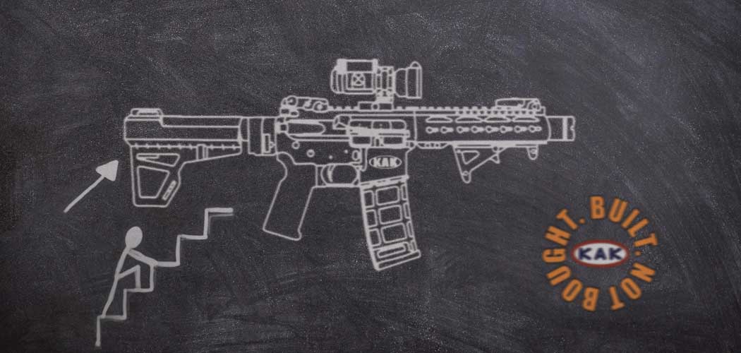
The process of building your very own AR-15 can be thought as a daunting task, but an exciting one. We’re here to help aleviate some of your hesitancy, if any. This easy step-by-step instruction guide (with visuals) will give you the tools you need on how to build your very own AR-15. Think of it as one of those popular instructional/reference books, like “How To Build An AR-15 For Dummies” if you wish, suitable for beginners.
People often ask:
An overview of parts and kits necessary to build your AR-15:
Don’t need an overview? Jump to our step-by-step guide to start your build. Or download our AR-15 complete assembly guide in PDF.
KAK Industry AR-15 Parts List
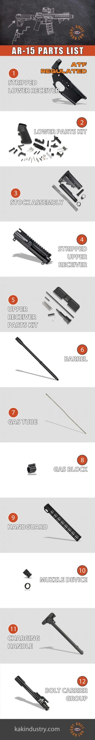
Our first step in making this process an easy one was to complile a list of all the KAK Industry components you’ll need to start your build. This list is composed of twelve parts and kits essential to get you going. Each one is explained in detail below to answer any questions you might have throughout this process.
Shop the Complete List of AR-15 Parts
Stripped Lower Receiver
1Thanks to the ATF, the hardest part will be purchasing your stripped lower receiver. At KAK Industry we offer both a K15 billet and KF-15 forged version lower receiver.
As you well know, items that are regulated by the ATF have restrictions and requirements. This component will only ship to a Federal Firearm License (FFL) holder. If you are not an FFL holder, you can contact your local FFL dealer prior to placing your order to ensure they are still accepting transfers.
Upon placing your order with KAK Industry, for the lower receiver, you will be requested to provide a copy of your FFL license or your local dealer’s license at checkout. We also accept proof of FFL via email if a copy is not available at time of placing your order online.
KAK Industry will then ship your lower receiver to you, if you are an FFL holder, or to your local dealer of choice.
What’s the difference between a forged vs. billet lower receiver?
Our forged lower receiver is machined from quality USA produced 7075-T6 heat-treated aluminum forgings with low weight and high stress resistance. Making it an excellent choice due to its well-balanced set of properties. It is a preferred choice for the aerospace, marine, and transportation industries which is why it is a great choice for the firearm industry.
Our billet lower receiver is precision CNC machined from a solid block of aircraft grade aluminum. All internal dimensions are cut to the proper military dimensions. The receivers are media blasted and have a deep lustrious hard coat anodizing. They match perfectly with our forged upper receivers. KAK Industry’s billet AR-15 lower receivers are the perfect foundation for your next build.
Which is better, a forged or billet lower receiver?
As far as pricing goes, the billet lowers are substatntially more money than forged lowers. The billets are more expensive because of the manufacturing process. So, if you are going for that budget build the forged lower receivers would be a better choice.
As far as the strongest type of lower receiver on the market…the consensus is that the forged aluminum is the strongest. The higher strength rating means it can also take more abuse in the field. In the end, it’s ultimately your choice as there is such a close competition between the two.
Shop the Complete List of AR-15 Parts
Lower Parts Kit
2Our AR-15 lower parts kit features KAK Industry produced parts throughout. It includes a mil-spec trigger group, billet trigger guard, standard A2 handle, and mil-spec springs. Each 100% made in the USA. This kit is one of the best lower parts kit in the industry.

AR-15 Complete Lower Parts Kit Assembly
An overview of steps necessary to build your complete lower parts kit:
STEP 1: Assemble Trigger & Trigger Spring
Assemble the trigger and trigger spring by first ensuring the metal wire connecting both coils of the spring rest underneath the sear (the front, flat part of the trigger). Slide the first coil of the spring over the trigger pin hole, and then repeat on the opposite side for second coil.


STEP 2: Install Disconnector Spring
Pull the disconnector spring from your AR-15 complete lower parts kit. The disconnector spring and the bolt catch plunger spring are very similar which makes it harder for you to identify. As a tip, the disconnector spring has a flared base on the bottom end on the spring.
The flared base is to go in the cutout of the trigger. Hold the trigger vertically and insert the flared base of the spring into the cutout hole of the trigger. It will be a tight fit, so apply some pressure to ensure the bottom of the spring is fully seated. Some recommend using a 3/32″ pin punch tool to gently push the spring down but we did not find this necessary.


STEP 3: Assemble Hammer & Hammer Spring
Hold the hammer so that the hammer pin holes are on top and you can see each stud on left and right. The tip of the hammer should be facing you. In the other hand, hold the hammer spring so that the coils are pointing away from you. Angle the stud toward the left coil while pulling the right coil away to make room. Once the left stud is in place you should easily be able to rotate the right stud so that it is inserted into the right coil. Compare your result to the step three image below.


STEP 4: Install Trigger & Disconnector
You will need the complete trigger assembly as seen in step 2 along with the disconnector and trigger pin. Please note that the trigger pin and the hammer pin are the exact same pins, either one will work. Place the disconnector into the cavity of the complete trigger assembly so that the holes line up on either side. The disconnector notch should rest on top of the disconnector spring, see image below.
Lubricate the trigger pin hole with lubricating gun oil. Place the trigger and disconnector assembly into the lower receiver. Gently press down on the trigger and disconnector assembly until you see all the trigger pin holes line up in the side of the lower receiver. Insert the trigger pin while the holes are lined up perfectly. The pin should be inserted into either side of the receiver with the grooves on the trigger pin going in first.
Use the gunsmithing hammer to gently tap the trigger pin in place. Continue tapping the trigger pin until it’s flush with both sides of the receiver. Double check the trigger and disconnector assembly inside the fire control cavity. The ends of the trigger spring should rest on the floor of the fire control cavity. And make sure both trigger spring coils are still in place around the studs of the trigger pin holes.


STEP 5: Install Hammer & Hammer Pin
Lubricate the hammer pin hole with lubricating gun oil. Hold the hammer and hammer spring assembly as shown in step 3 image below. Gently squeeze the legs of the hammer spring and drop, legs of spring first, into the fire control cavity. Start to bend legs so that they lay to the right closest to the magazine button cavity while you pull the hammer to the left. The hammer spring legs should rest atop the studs towards the outside of the trigger coils. The studs and coil springs of the hammer should line up on either side of the hammer pin holes of the lower receiver.
Insert the hammer pin while the holes are lined up perfectly. The pin should be inserted into either side of the receiver with the grooves on the hammer pin going in first.
Use the gunsmithing hammer to gently tap the hammer pin in place. Continue tapping the hammer pin until it’s flush with both sides of the receiver.


STEP 6: Install Trigger Guard
You can skip this step if you are working with a KAK Industry billet lower receiver. For forged lower receivers install the trigger guard. Find the roll pin hole on the trigger guard. It is the largest of the holes and is not threaded. Align the trigger guard’s rear pin hole with the two holes on the lower receiver on side closest to the trigger.
Because the roll pin is a very tight fit, use the lubricating gun oil and gunsmithing hammer to gently tap the roll pin into place. You may need to use the 3/32″ punch in addition to the hammer to make sure the pin is in place and flush on both sides. The rubber part of the needle nose pliers may be used to place under the holes of the lower receiver to reduce the risk of bending or breaking the lower receiver.
Next align the other side of the trigger guard with that of the lower receiver. Start screwing in the set screw. To finish screwing in the set screw us an allen wrench or hex key until the screw is flush on the other end of the hole on the lower receiver.


STEP 7: Install Magazine Catch & Magazine Release
Take the magazine catch and insert the threaded portion through the magazine hole in the left side of the receiver. The threaded portion should stick through the other side of the receiver to install the magazine catch spring and magazine release button.
With your thumb holding down the magazine catch install the magazine catch spring. This spring is the widest of all springs in the kit with the fewest coils. Next, thread the magazine release button onto the magazine catch while still holding it down with your thumb.
You will need to thread the button until it’s just about flush with the hole in the receiver. It may help to apply some lubricating gun oil to both the magazine release button and threads. It may help to install the button with the 5/32″ punch. You can use an empty magazine to test the magazine catch and magazine release button to make sure it functions.


STEP 8: Install Bolt Catch
Collect the following items out of the complete lower parts kit: bolt catch lever, bolt catch plunger spring, bolt catch plunger, and bolt catch roll pin. It is recommended you use masking tape on the receiver around the bolt catch mount and roll pin holes. This will potentially prevent the risk of damaging and/or scratching the anodized finish on the receiver.
It is recommended to use lubricating gun oil on the bolt catch lever, bolt catch spring, and bolt catch roll pin holes. Insert the spring into the bolt catch hole. Next, insert the plunger atop the spring.
Get the bolt catch roll pin “started”, by partially inserting the roll pin inside the bolt catch roll pin hole. Use the gunsmithing hammer to gently tap it inside the hole BUT stop just before it goes through the first side to allow the bolt catch lever to be inserted. Now, insert the bolt catch so it’s resting atop the plunger.
You will need to apply some pressure to align the holes. Once the holes are aligned, continue tapping the roll pin into place until it is inserted on both sides. Once installed, the pin should be just slightly recessed inside each hole. It will be necessary to use KAK Industry’s bolt catch roll pin starter punch and the walts finish tool to get to the pin recessed inside.


STEP 9: Install Front Pivot Pin
For step nine, you’ll need the front pivot pin, pivot pin detent, and pivot detent spring. Take the detent spring and place it into the pivot pin detent hole. The pivot detent spring is the same as the takedown detent spring; the thicker one is the safety detent spring which will not fit in the pivot pin detent hole.
Next, grab the pivot pin detent; it is the same as the takedown pin detent. It is recommended that you use pliers to insert the pivot pin detent atop the spring. The pin will need to be compressed down into the hole. You can use a dull razor blade or knife to hold down the pivot pin detent and keep it compressed. The spring and pin detent will need to remain compressed while inserting the front pivot pin.
As the parts are kept compressed, insert the front pivot pin into its mounting hole with the channel of the pin facing towards the detent pin. Use lubricating gun oil to help with the tight fit. The blade or knife can be removed once the detent pin has reached the channel of the front pivot pin. The detent pin will lock into the channel. Keep inserting the front pivot pin into the receiver’s mounting holes and until it fully seated in place.


STEP 10: Install Safety Selector & Pistol Grip
Collect the following parts: safety selector lever, safety detent pin, safety detent spring, pistol grip, hex bolt screw, and lock washer from the complete lower parts kit. The safety selector lever and pistol grip will need to be installed together to help retain the safety detent spring and detent pin. Start by using the lubricating gun oil and lubricate the safety pin hole. Then, insert the safety selector lever through the hole.
Next, you will need to flip the lower receiver upside down to insert the safety detent pin into the detent hole, pointed end first. The detent hole is located right above the safety selector lever hole. It is the closest hole to the safety selector lever hole when the lower receiver is flipped upside down.
Now insert the safety detent spring into the hole located on top of the pistol grip. Begin to install the pistol grip onto its mount. You will need to make sure the detent spring aligns with the safety detent pin.
Once the pistol grip is seated on to the lower receiver make sure the bolt hole and grip hole are aligned, insert the hex bolt screw and washer. You can use a 3/16″ Allen key to tighten until “hand-tight” and secure the pistol grip.


STEP 11: Install Rear Takedown Pin
For this step, you’ll need to pull the rear takedown pin and takedown pin detent. Use lubricating fun oil to lubricate the takedown pin and insert it into the pin hole in the right side of the lower receiver. On the back of the lower receiver insert the takedown pin detent into the small hole located next to the latch plate mount. You will find this hole just below the buffer tube housing.


STEP 12: Install Buffer Tube & Buffer Retainer
Collect the following parts: takedown detent spring, buffer tube, castle nut, latch plate, buffer retainer, and buffer retainer spring. You will find the buffer tube, castle nut, and latch plate in the M4 carbine stock assembly kit. You will also need KAK Industry’s castle nut multi tool.
Start by inserting the rear takedown detent spring atop the takedown pin detent in the same hole as step eleven. Then retrieve the buffer tube and install the castle nut onto the threads. Make sure to thread the nut to the end of the threads. The crown of the castle nut should be facing the rear of the buffer tube. Next, grab the latch plate and slide it onto the threads behind the castle nut.
Thread the buffer tube into the housing of the buffer tube assembly. The latch plate should touch the rear takedown detent spring. Grab the buffer retainer and buffer retainer spring. The buffer retainer spring will need to be inserted into the hole of the buffer tube housing’s threads.
Next, insert the buffer retainer atop the spring. You will need to compress it with the 5/32″ roll pin punch. With the compression applied to the buffer retainer, thread the buffer tube into place until it meets the buffer retainer.
Make sure the lip of the buffer tubes rests on the retainer. It should be next to the protruding nipple located on the middle of the retainer. This will make sure the buffer and buffer and the buffer retainer spring are properly seated once your rifle or pistol is assembled.
Make sure the takedown detent spring is resting in its hole. You will need to compress the spring by pressing the latch plate on top of it. Keep gently compressing on the latch plate until it is flush with the backside of the buffer tube housing. At this time, you can then thread the castle nut up against the latch plate, make sure it is flush. Once flush, slide your castle nut multi tool over the castle nut and tighten the castle nut.


Stock Assembly
3KAK Industry’s mil-spec carbine stock assembly kit contains a 6-position mil-spec buffer tube, castle nut, standard mil-spec endplate or latch plate, chrome silicon carbine buffer spring, standard carbine buffer, and an M4 style stock with latch and sling swivel. Perfect for your future rifle build.
M4 Carbine Stock Assembly
STEP 13: Install M4 Stock & Standard Carbine Buffer
In step 12, we’ve already covered installation of the buffer tube and buffer retainer because some of the process included parts from the M4 carbine stock assembly kit. To finish the stock installation you will need to retrieve the M4 stock, carbine buffer spring, and standard carbine buffer from the same kit.
Insert the standard carbine buffer into the back end of the carbine buffer spring. The front end of the spring slides into the buffer tube. Push it all the way in, it will compress the buffer retainer and will snap over. At that point, it’s held in place.
To install the M4 stock body, insert it on the end of the buffer tube. Then pull the stock release so that you can slide it over to the end. That allows you to move the stock to different positions.


Stripped Upper Receiver
4Our forged AR-15 stripped upper receiver is forged from 7075-T6 aluminum. The stripped upper receiver is precision-machined to M16/M4 specification and features M4 feedramps. The upper receivers match perfectly with our billet lower receivers.
Upper Receiver Parts Kit
5KAK Industry’s upper completion kit includes an ejection port cover, ejection port cover rod with clip and an ejection port cover spring, forward assist, forward assist spring, and forward assist roll pin. Everything you need to complete your stripped upper.
Complete Upper Receiver Assembly
An overview of steps necessary to build your complete upper receiver:
STEP 14: Install Forward Assist
In this step you’ll need the stripped, forged upper receiver and the following parts from the upper receiver parts kit: forward assist plunger, forward assist spring, and forward assist roll pin.
First, hold your forward assist roll pin over the end of the forged upper receiver using the needle nose pliers. This will help you get it started by compressing the pin by a little bit. Using the gunsmithing hammer tap the pin just so it’s getting started and then release your nose pliers’ grips.
Then take your forward assist plunger and forward assist spring. Slide your spring over the front end of your plunger. Pull the spring back so that you can see the flat end of the plunger. That flat part needs to be inserted in towards your roll pin. Push the plunger in until flush. Grab your gunsmithing hammer and start tapping in the roll pin. You will notice that after a few taps the plunger will start to catch and not come back out. To finish tapping in your roll pin you can use a 5/32″ roll pin punch. Place the punch over the pin and finish tapping it in place with the gunsmithing hammer until it is flush.


STEP 15: Install Trapdoor Ejection Port Cover
Pull the following parts from the upper receiver parts kit: ejection port c-clip, ejection port cover rod, trapdoor ejection port cover, and ejection port cover spring, along with your upper receiver assembly.
The c-clip will secure the rod that holds the trapdoor cover and spring to the forward assist assembly. Use some needle nose pliers to hold the c-clip for installation. Position the c-clip over the groove in the retaining pin and tap it into place with a gunsmithing hammer.
Next, oil the rod using lubricating gun oil. Place the upper receiver assembly on its side with the ejection port facing up. Start by sliding the smooth end of the rod through the right of the upper receiver (the end opposite the c-clip). Do not slide all the way through as you will need to install the trapdoor ejection port cover along with the rod.
Place the trapdoor ejection port cover in place and slide the rod through the right side just until it appears in the gap where the ejection port cover spring will be installed. Now lay the spring into position with the long end on the right side pointed up. Holding the left side of the spring rotate the right side of the spring away from you so that the long end faces down pointing towards you. Then insert the rod all the way through the spring.
Make sure to test the trapdoor cover for proper function.


Barrel
6A perfect addition to your build would be our value-line 5.56 nato 16 inch mid melonite barrel. These barrels proved to be so popular that we decided to make them a regular item.
STEP 16: Install Barrel
Grab your value-line 5.56 NATO 16 inch mid melonite barrel along with your upper receiver assembly. You will need to pull the barrel nut and the barrel nut wrench from your purchase of our M-LOK handguards. These parts are included with the handguard.
Ensure that the upper receiver is free of any defects or damage to the threads. Apply an anti-seize compound such as Aeroshell 64 to the threading on the receiver. Insert the barrel into the upper receiver. Ensure that the barrel index pin is fully seated in the index pin slot and that the barrel is seated in the upper so that the lip of the receiver is touching the lip of the barrel extension.
Keeping the barrel in the receiver, thread the barrel nut that was included with the handguard onto the upper receiver assembly. Be sure not to cross thread and seat the barrel nut firmly with hand pressure.
Install the upper receiver into a quality fixture or vice that prevents excessive torque on either the upper receiver or the barrel.
Using a torque wrench and either the supplied wrench or a standard castle nut barrel wrench, tighten the barrel nut using the following procedure: tighten the barrel nut to 35 foot pounds, loosen the barrel nut, tighten the barrel nut to 35 foot pounds, loosen the barrel nut, and then tighten the barrel nut one final time to 35-55 foot pounds.


Gas Tube
7Use our mid length gas tube to attach to our gas block. This will provide a secure path for gasses to travel back which will force the bolt carrier group to cycle. If you do not choose the proper length gas tube for your barrel it can cause your firearm to not cycle properly, or wear itself out too quickly and possibly jam.
Gas Block
8The steel .750 low profile gas blocks are machined in-house from 4140 steel and finished with a blasted manganese phosphate finish. These are the same gas blocks used in our upper assemblies and comes complete with set screws and gas tube roll pin ready to install on your .750 diameter barrel. Very low proflie to clear most rail systems.
STEP 17: Install Gas Tube & Gas Block
In this step you will need the upper barrel assembly, mid length gas tube, .750 low profile gas block (the gas block comes with gas tube roll pin and gas block set screws). You will need to use medium strength thread locker (Loctite®) on the gas block set screws.
Start with the gas block and gas tube roll pin. Use the needle nose pliers to hold the pin in place. Tap with a gunsmithing hammer until you just get started. Release the pliers from the pin.
Now take your gas tube and insert it into the gas block tube tunnel. You may need to move the pin back out a little for the gas tube to get in position. You want the dip on the gas tube to go up and forward while lining up the holes on the other side. Using a roll pin punch and gunsmithing hammer finish tapping in the pin until flush.
Slide the gas block tube assembly onto the barrel. Make sure the gas tube slides into the upper receiver assembly. The gas port should align properly with the gas block. Next, screw in the set screws using an allen wrench.


Handguard
9The KAK Industry line of MLOK compatabile handguards provide you with a high quality rigid mounting system at a great price. Designed and manufactured in the USA. See our MLOK handguard undergo the brutal torture test…
STEP 18: Install Handguard
These AR-15 handguards are intended for use on mil-spec style upper receivers. Installation on certain billet or non standard upper receivers may require modification of the handguard or receiver. Please note that modifying the handguard will void any warranty. Please follow the instructions below to ensure the safest and most reliable installation of your new handguard.
Slide the handguard over the barrel nut allowing the index tabs to fit on each side of the upper receiver. To fit some bulkier billet upper receivers, these tabs may need to be modified or removed. This will void any warranty and the part will not be returnable.
The handguard installs with two aluminum clamps. These clamps can be inserted from either side. Tightening these clamps pulls the handguard down into the barrel nut ensuring that it will not move and that the top rail stays level. Install the clamps using the following procedure:
a. Place on clamp on each side of the barrel nut
b. Apply a small amount of medium strength thread locker to each cap screw
c. Thread two screws into the clamps from the side with the larger diameter hole
d. Alternately tighten the two screws until they both reach 45 inch pounds. Check each screw to confirm the proper torque.
If it’s easier you can print out our KAK Free Float Handguard Installation Instructions. These instructions go over barrel installation as well.


Muzzle Device
10The KAK Industry 1/2-28 mini compensator features a unique design with a closed end and holes in the upward position only. This will help to redirect pressure and high velocity gases. And reduces the muzzle rise which allows faster and more accurate shot placement. The mini compensator is 1/2″ shorter than the standard KAK compensators.
STEP 19: Install Muzzle Device
The KAK Industry 1/2-28 mini compensator is to be installed as the muzzle device next. First, start out by applying some AeroShell Grease 64 on the threads of the barrel. Next grab the 1/2″ crush washer. You will want to make sure the smaller side of the crush washer is placed against the barrel. The larger side will be facing you flaring outwards.
Go ahead and hand-tighten the muzzle device by threading it onto the barrel. Then use the castle nut multi tool as a wrench and start tightening down. If you start feeling a lot of resistance you can then back it off and then start tightening again. Tightening, loosening, tightening loosening until completely installed.


Charging Handle
11The standard AR-15 charging handle at KAK Industry features a standard latch design which fits AR-15 rifles and pistols. It is protected by a mil-spec hardcoat anodized finish in black.
Bolt Carrier Group
12The nitride auto 5.56 bolt carrier group (BCG) would be the next part you throw in your shopping cart. It features a nitride coating throughout and is magnetic particle inspection (MPI) tested and marked. Includes o-ring extractor helper to run under all conditions.
What does MPI tested mean?
An item that has passed a magnetic particle inspection test, better known as MPI, means that the item has been tested and marked or certified. The MPI process puts a magnetic field into the part. The piece can be magnetized by direct or indirect magnetization. This MPI certification is a highly sought after quality control check. Reason being is that the testing method can detect surface and subsurface flaws in in the BCG’s materials. Understanding how a bolt carrier group works helps put this testing into context within the rifle’s cycling system.
STEP 20: Install Charging Handle & Bolt Carrier Group
And now we’re going to install the charging handle. Insert your charging handle into the upper receiver, but don’t slide it in all the way.
Then grab your bolt carrier group and head first slide the bolt carrier group into the upper receiver starting at an angle. Push the bolt carrier group in and the charging handle will follow.


STEP 21: Combine Upper & Lower Assemblies
The upper and lower receivers can now be joined together. First, make sure your hammer is cocked and the safety is on. Make sure your pivot and takedown pins are fully extended. Your pivot pin will secure these two receivers. Next, line up the pivot pin with the pin hole of the upper receiver and push the pin all the way in. Then you can close the two halves together and push in the takedown pin.
That completes combining the two halves together. But you will want to do some simple function checks. Keep following us on how to perform these tests to make sure your firearm is fully functioning.


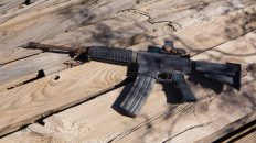
What do you think? Are you ready to build your AR-15?
#kakbuild #askkak #builtnotbought #doityourself

I’m not seeing the AR-15 Complete Build pdf download. Where is the link?
Hi Darrin! Thanks for pointing that out. I just finished updating the link but plan to add more content soon. Hope it helps!
Very clear and thorough instructions for putting together an AR-15.
I know you may be too busy and might not be able to, but would you consider publishing similar guides for the AR-10 and AR-9 platforms as well?
Thank you Benny! So glad to hear that it was helpful. I will add the AR-10 and AR-9 how-to guides to the to-do list.